The Helix Part V …
Hi all,
Well, I have reached another milestone with the completion of the helix. When I say “completion”, it’s not 100% complete as I plan to put some ‘guard sides’ up on each of the layers to afford some protection to prevent trains from taking a plunge if they derail, but I plan to do this later on. But otherwise, the main structure is finished.
Following on from the last post, the next stage was to set the height of the first (bottom) layer to the correct height as this would then set the grade for the whole helix.
My initial attempt at this didn’t go so well, as I think I miscalculated the height of each sequential riser, eight in all. The reason I say this, is when the rest of the layers were lifted up into position, something didn’t look right. Some segments of the helix looked steeper than others.
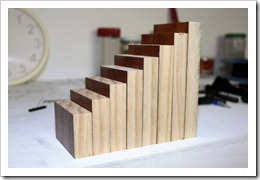
The picture above shows the helix layers lifted up and spaced with temporary blocks at the correct height. This picture was taken with the first layer risers that were incorrect. To lift each layer up, it was just a matter of carefully lifting the whole thing and placing the temporary blocks in place at each of the eight support locations around the circumference. This was repeated for each layer.
After some later discussion with my consultant (Andrew), and after some more measurements and calculations, we came to the conclusion that I had indeed stuffed up the initial height calculations.
Some new risers were then cut, and fixed in position.
The pictures above shows the new first layer risers all cut and installed. These were glued to the L girders as well as the ply roadbed. After these were fitted, the whole helix looked much better and with even grades.
I had originally planned to make notched risers to support the helix at the eight points, but could not work out a way to accurately cut these notches. After some discussion again with Andrew, I decided to still use the 2×1 as the risers on the inside and outside, but just glue blocks in place to support the roadbed layers. See the pictures below.
The blocks were cut from some of the timber I had used to make the temporary spacer blocks. They were cut to about 15mm thick so as to not encroach too much onto the track and to allow enough room for the longest piece of rollingstock to pass through with clearance. The blocks are only glued to the risers and not the plywood. This should allow for any slight expansion and contraction in the timber.
Just to finish off, below are a couple of shots of the finished structure. I have also fitted the transition piece of ply roadbed from the top layer to where the spline will be attached at the 70 inch level. I am surprised at how rigid the whole structure is now.
Where you can see the red clamp, I have placed a temporary riser to support the transition section where the spline will attach.
At some stage, I want to temporarily connect a throttle of some sort to test run a loco up the helix.
Cheers for now.
Posted on May 24, 2012, in Benchwork, Trackwork and tagged helix, riser, roadbed, spline. Bookmark the permalink. Leave a comment.


Leave a comment
Comments 0