Blog Archives
The Helix Part V …
Hi all,
Well, I have reached another milestone with the completion of the helix. When I say “completion”, it’s not 100% complete as I plan to put some ‘guard sides’ up on each of the layers to afford some protection to prevent trains from taking a plunge if they derail, but I plan to do this later on. But otherwise, the main structure is finished.
Following on from the last post, the next stage was to set the height of the first (bottom) layer to the correct height as this would then set the grade for the whole helix.
My initial attempt at this didn’t go so well, as I think I miscalculated the height of each sequential riser, eight in all. The reason I say this, is when the rest of the layers were lifted up into position, something didn’t look right. Some segments of the helix looked steeper than others.
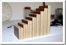
The picture above shows the helix layers lifted up and spaced with temporary blocks at the correct height. This picture was taken with the first layer risers that were incorrect. To lift each layer up, it was just a matter of carefully lifting the whole thing and placing the temporary blocks in place at each of the eight support locations around the circumference. This was repeated for each layer.
After some later discussion with my consultant (Andrew), and after some more measurements and calculations, we came to the conclusion that I had indeed stuffed up the initial height calculations.
Some new risers were then cut, and fixed in position.
The pictures above shows the new first layer risers all cut and installed. These were glued to the L girders as well as the ply roadbed. After these were fitted, the whole helix looked much better and with even grades.
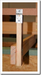
I had originally planned to make notched risers to support the helix at the eight points, but could not work out a way to accurately cut these notches. After some discussion again with Andrew, I decided to still use the 2×1 as the risers on the inside and outside, but just glue blocks in place to support the roadbed layers. See the pictures below.
The blocks were cut from some of the timber I had used to make the temporary spacer blocks. They were cut to about 15mm thick so as to not encroach too much onto the track and to allow enough room for the longest piece of rollingstock to pass through with clearance. The blocks are only glued to the risers and not the plywood. This should allow for any slight expansion and contraction in the timber.
Just to finish off, below are a couple of shots of the finished structure. I have also fitted the transition piece of ply roadbed from the top layer to where the spline will be attached at the 70 inch level. I am surprised at how rigid the whole structure is now.
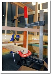
Where you can see the red clamp, I have placed a temporary riser to support the transition section where the spline will attach.
At some stage, I want to temporarily connect a throttle of some sort to test run a loco up the helix.
Cheers for now.
Setting the grade …
In this post, I will attempt to explain how I have gone about setting the grade for the spline from the bridge at Chilcott’s Creek, through Kankool and currently halfway to the teardrop. The same process will continue right through to Ardglen where it levels out halfway through the tunnel. Apologies for the length of this post, but I thought that putting it all in one post would be easier than splitting it.
Following on from the last post where I explained how I marked the 42” datum level around the layout using the water level, the next thing I did was to flick a chalk line on the walls against the marks made using the water level. I now had my datum “zero” level around the walls to Kankool.
When it came to making the marks along the peninsula benchwork, I soon realised that where the 42” level was, was about halfway up the joists sitting on the main girders. This initially proved tricky to get a true datum level, so I decided to mark out the 70” top track level on the peninsula walls using stringlines. I now basically had two datum levels from where to mark out riser heights.
In all the articles I have seen about spline roadbed, they always say to fix the risers in place first where you want the roadbed. I couldn’t see how this would work for two reasons :-
- I didn’t know exactly the route the roadbed would take. That’s the beauty of the spline – it’s adjustable.
- How do you set the riser heights, and therefore the grade, without having the spline in place to check for dips or bumps?
So, hence the reason for me building the spline flat on temporary joists, then when the time comes, fix in place the proper joists at set intervals, and then the process of setting the grade can commence.
The beauty of the 3rdPlanIt program is that you can set a grade and have it display the track height (elevation) at any location along the track.
The screen capture above is from the layout drawing in 3rdPlanIt and shows the locations of the joists along the route. The lines actually are the centrelines of the risers rather than the joists, but there is only a difference of about 20mm.
Once the grade has been set in 3rdPlanIt, a text marker can be placed along the track that shows the elevation at that particular point.
The screen capture above now shows the elevation markers at the joists. The values shown are based on a zero elevation at floor level, so because my datum level is 42”, I just took the difference between the two. So now I had my roadbed heights, I could now mark these at each riser location. Using a large square and spirit level, I drew vertical lines on the walls that lined up with where the risers would attach to the joists. The roadbed levels were then made around the walls by just measuring up from the 42” datum line and making a mark.
When it came to making these marks along the peninsula walls, I just reversed the process by taking the difference between the roadbed elevation and the 70” datum and measured down the wall ‘stud’.
Now that I had all the elevations marked out, it came time to cut up some timber to use for risers. Under the single track areas I used some 2×1 DAR and under the double track areas at Kankool, some 3×1.
I initially started to attach the risers to the joists first with the aim of then attaching the roadbed to the top of the riser later, but this proved to be not the right way to do it. I instead decided to glue the riser to the underside of the spline first, using Liquid Nails, and when set, I could then fix the riser in position. This would then also allow for slight twisting of the spline to ensure it is level.
The photo above shows a riser being glued and clamped to the spline. Note the riser is only temporarily clamped to the joist at this stage.
Now, a short side note. Up until early this week, I had fixed the roadbed/risers in position all the way through Kankool and half way down the first peninsular. The grade was looking good, then for some reason, when I was looking at the overall layout drawing, I realised that when I first drew the plan, I hadn’t allowed for the peninsula wall on the teardrop section, and consequently discovered I hadn’t allowed for enough scene depth behind the track at both Pangela on the top level and the corresponding track underneath it. AARRGGH!!!! So after about two hours redrawing this section of the layout and pushing the track out further to give around 400mm scene depth, I got it looking better. I then realised that I would have to recheck the grade through this section. When I did, it had changed slightly, which now meant all the roadbed I had previously fixed in place was about 7 mm high at each riser. *@#$%!!!!!!
Also, during this time when fixing some risers along the first peninsula, I came across another issue. I think I must have used a cheap glue when fixing the riser to the underside of the spline, because I had to twist a couple of risers quite a bit to get the spline level at that point, and it was here I noticed that the glue was letting go. So a solution had to be found. I went through a number of ideas, but I think this will solve the problem.
I had noticed that the problem lay generally on the inside of curves where I had to twist the spline to get it level. So a quick trip to the hardware store to get some hoop iron and small wood screws. Short sections were then cut and bent to shape for each location and screwed to the spline and riser. I may have to rethink the riser to spline attachment process, but for now I have changed to a known brand of adhesive, namely Max Bond. I may have to use the method described here and nail the spline to the riser to compliment the glue. See pages 20 and 21.
So, after that issue was sorted out, I printed out another layout drawing showing the revised elevation heights and proceeded to remark the heights and drop the risers down. In the meantime I have also added more joists on the teardrop and started laying out more spline along the other side of this peninsula.
Now, back to the elevation setting process.
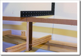
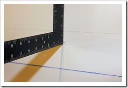
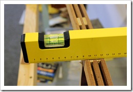
With the spline sitting on temporary risers, clamped roughly at the right height, I had to devise a way of accurately getting the riser at the right height. I ended up using a steel right angle square held against the wall at each location with it’s bottom edge lined up with the height mark, and either raised or lowered the riser until it touched the square. The riser was then clamped in position and screwed to the joist, after checking for level (see below). A small piece of scrap masonite was placed on top of the spline to allow for the foam roadbed, as all roadbed heights referred back to this datum ie 42”.
The two images above show the square in position against the wall with the masonite packer, and a close-up of the elevation mark on the wall (the green line) and the 42” datum (the blue chalk line). The red line was the previous elevation mark prior to the track changes on the peninsula mentioned above. At this point in the process, before fixing the riser, a spirit level was placed on top of the spline to check for level.
Well, that’s about where things are up to at the moment. I hope it all makes sense, as sometimes I find it difficult to put into words how I do something. As mentioned above, I have started to install joists further along the other side of the teardrop peninsula so I can resume spline construction here.
Over the last week I have also got my hands on some more photos of the area. I posted a message on RailPage Australia asking for photos of the signals and structures at Kankool, Ardglen and Pangela. I eventually heard from a couple of blokes who are ex train drivers, and are both sourcing more stuff for me. Some I have already received from one are real beauties. If anyone else out there has any photos of the area, please let me know.
Cheers for now.

