Blog Archives
Re-laying track
Well I can’t believe it’s 12 months since my last post. I just never seemed to get around to posting anything.
One of the biggest tasks undertaken was to re-glue the rails to the CV ties all the way from Kankool to Ardglen. I had discovered that the rail had started to lift in quite a few locations. I am still unsure what the cause was, but I’m putting it down to my initial glue mixture of contact cement and MEK.
I had been very apprehensive about doing it, but realised I had to just bite the bullet. Subsequently over about a six week period, I lifted 38 metres of rail, cleaned the old glue of the base and also off the CV ties, and using Pliobond straight from the tube, applied it to both rail and ties and re-laid the rail back in place. The process wasn’t too bad, as it was still all pre-curved.
During the process, I also increased the gap between lengths of rail from virtually nothing to around the thickness of a piece of paper.
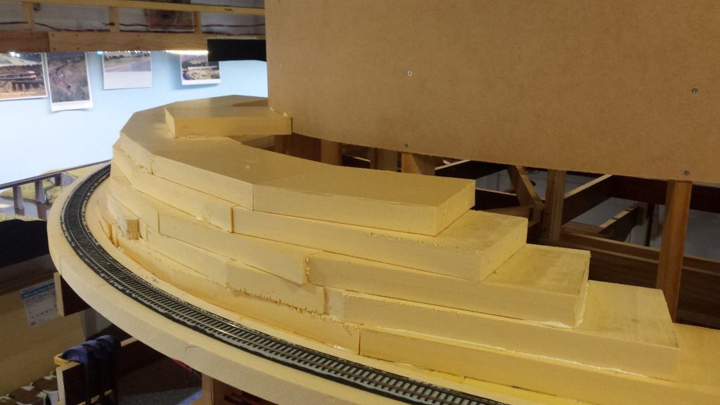
The next biggest task had been to install more scenery foam nearly all the way to where Ardglen quarry is located. This was roughed in using previous techniques and is yet to be carved to shape.
More backscene board was installed, again, up to where the quarry is located.
Upper deck progress …
Hi all,
Since my last post, I have been busy with work on the upper deck above the Chilcott’s Ck to Kankool section.
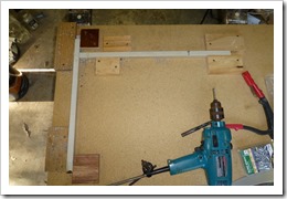
To support the upper deck valance and future lighting, steel brackets were fabricated from second hand 20x20mm square tube, along with bracing made from thin steel plate.
A simple timber jig was made to hold the pieces of tube in place whilst the brace plate was attached using pop rivets.
These brackets were then screwed to the wall at strategic locations at wall studs.
After the initial installation of these brackets, I discovered a potential flaw in my design. The two rivets fixing the brace plate to the vertical tube were shearing off with only minimal downward force being exerted at the outer end of the horizontal tube. Now, I’m not sure whether it was actual rivet failure or what, so I decided to replace these rivets with a 3/16” bolt/spring washer/nut combination. The result is a much stronger feeling bracket.
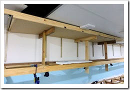
I had also decided to install a ceiling above each scene, as I didn’t fancy the idea of being able to see the open benchwork when looking along the scene from one end. Once painted, I also think it will assist in spreading the light onto the scene.
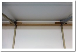
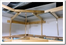
The ceiling is made from sheets of 3.2mm MDF (2440x1220mm). This required the installation of a timber sub-frame built around the steel brackets to allow for the securing of the ceiling. 2×1 DAR pine was used.
More framing was also installed in the corner to support the backscene and ceiling.
A ceiling section was cut to size from the MDF and secured to the timber frame using Liquid Nails and small gauge countersunk screws. The adhesive was also applied to the steel tube. Temporary supports were used to hold the ceiling in place whilst fixing the screws. After the screws were installed, extra temporary supports were fitted to force the ceiling against the steel tube whilst the adhesive cured.
The ceiling section in the corner proved to be quite tricky to cut to size, but by using accurate measurements, I ended up with a piece that fitted perfectly.
A couple more sections of backscene was also installed, including the piece in the corner.
These sections of backscene have no need to extend completely down to the benchwork, as the track level will be around where the lower edge of the MDF is in the picture above, and the majority of scenery here behind the track will be hills covered with trees.
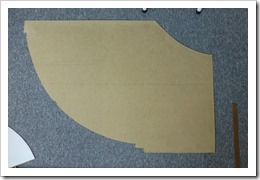
I also started playing around with how I will locate the Kankool lever frame into the fascia. The picture below shows a mock-up of what I hope to achieve.
The MDF immediately behind the frame will be the scene fascia and the curved piece in front is to indicate another section of fascia that will serve as ‘protection’ for the frame. More on this later.
Cheers.


