Blog Archives
Track Detailing – Part I …
Posted by Ian Millard
Hi all,
Just recently I have started painting the CV track in the Temple Court section.
The bare rails and plastic sleepers needed an undercoat prior to applying colour to them. I decided to use some Killrust etch grey undercoat, as I had used the same when painting the track on Bowen Creek. It was suitably thinned down to at least a 50:50 ratio and was applied by airbrush.
After the undercoat had dried, I decided to trial some colours in the short section leading off the staging yards. I masked off the tieplates and played around with finding a colour to paint these and the rail. Some time ago, I had gone to the local art supplies and purchased some acrylic paints that I thought would do the trick in painting the track. I ended up getting some colours that I had noted people were using from various weathering sites.
The mix was applied very lightly using the dry-brush method where there is minimal paint on the brush. I initially applied the Burnt Sienna straight, but it was too bright.
I then made a blend of Burnt Umber and Burnt Sienna, varying the mix until I got something that looked right. I wanted to get a base coat of a weathered rusty look but not too rusty.
The sleepers then needed a base colour, but at this point I was unsure of what to use. In studying a lot of photos I have, it’s very hard to see sleeper colour and it doesn’t help that the ballast is covering the sleepers in most areas, but I decided just to dry brush the Burnt Umber over the sleepers.
At this stage, I’m happy with the result. I think that once the ballast is applied and some weathering powders added, it will look OK.
I shall keep going like this in the Temple Court section, maybe slightly changing the rail colour as I go so as not to look too uniform.
After the track is painted, I’ll start on the scenery landforms.
Comments and feedback are most welcome.
Cheers.
Posted in Temple Court, Trackwork
Tags: burnt sienna, burnt umber, central valley model works, cvmw, tracklaying
Central Valley track laying – Part II(a) …
Posted by Ian Millard
Hi all,
Just a brief update today.
I laid the last piece of rail down for the section between the Down staging yards and the bottom of the helix. I must say that I’m really happy with how the CV track has gone down. I have even connected the track feeders to the bus wires. All that is required is to go back over the rail joins and see if any further strengthening is required. With pre-bending the rail, I got most joins to sit in place quite nicely, but I think I will go back and solder a piece of wire or flat bar on the non viewing side of the rail, similar to what I did with the PECO track in the helix.
The next task will be to paint the track with an etch grey primer then look at painting the tieplates and rail in a rust/rail brown colour.
Cheers.
Posted in Temple Court, Trackwork
Tags: central valley model works, cv, tracklaying, trackwork
Central Valley Track laying – Part II …
Posted by Ian Millard
Hi all,
On Monday I laid the first lengths of rail down on the Central Valley tie bases.
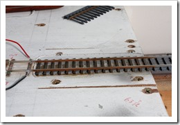
The first job was to install a short section of transition track between the PECO track and the CV track. This is located about where the train will enter the Temple Court scenicked section from the helix. The transition piece was required due to the different overall track heights between the PECO and the CV track, which was around one millimetre, with the CV track being less.
I managed to find a short length of Micro Engineering code 70 track and this was duly made to fit and feeder wires soldered in place.
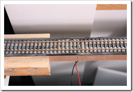
In the second picture you will notice quite a bit of adhesive. As the transition section could not sit flat on the foam due to the track height difference, the plan was to have it sit ‘suspended’ in the bed of glue. Liquid Nails was used, but once I had the track in position, I realised I had applied a tad too much glue! The excess glue will be removed with a Dremel ‘burr’ tool once set.
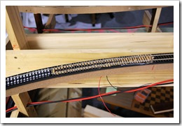
In the image below, I have pointed out that the rail joins are offset. This is similar to what I did when laying the PECO track in the helix. It’s always better to have rail joins staggered, as this helps with the flow of the track and the possibility of a kink is avoided.
I must now mention that the longer bit of rail at the top in the above image was pre-coated with the contact adhesive as well as the few CV ties that it would be glued to. Once it was in position, the rail was held down, located in the moulded tieplates, and MEK applied with a brush to the tieplates to activate the adhesive and make the bond. This will be explained further on.
I could now start laying rail on the CV track. But first I had to come up with a sequence of things to do. At the moment, this is what I have come up with:
1. Depending on the location, the rail needs to be pre-curved. The main reason for doing this is to alleviate the stresses on rail joins where the rail would be under tension and have a tendency to want to ‘spring’ out. The rail is curved using a Rail Roller from Fast Tracks.
The bend can be adjusted to suit whatever radius you have. I found that after a few passes through the tool, I achieved just the right amount for the rail to virtually sit in place on its own.
2. Once the rail has been curved, it is placed in position and a mark made at a suitable location for the feeder wire to be attached. With the semi-hollow nature of the spline roadbed, it allows the feeder wires to be pulled through the foam and spline. These will be hidden by the ballast later on.
So, a short piece of hook-up wire is soldered in place on the underside of the rail.
3. The underside of the rail is now cleaned with Methylated Spirits to ensure a good bond with the contact adhesive.
4. Once the rail is clean, the contact adhesive & MEK mixture is applied as a thin coating using a cotton bud.
5. The same adhesive is also applied to the tieplates on the CV track. Again a thin coating is all that is required and is applied by brush.
Both the rail and tieplates are left to dry for at least an hour.
6. Once the adhesive is dry, the rail is placed in position on the moulded tieplates, held down with light pressure with a small block of wood, and MEK is then applied to the rail/tieplate join with a brush. Keep pressure applied for about thirty seconds then move on. I only do about ten sleepers at a time.
At this point, I am only laying one rail. I’ll probably continue with one rail all the way to the staging yards, then come back and fix the second rail in place. I’m hoping I won’t need to use any gauges as the moulded tieplates form the ‘gauging’.
Overall I am very pleased with how it’s all going. A lot better and easier than I had imagined.
Cheers.
Posted in Electrical, Temple Court, Trackwork
Tags: central valley model works, cv, cvmw, mek, temple court, tie strips, tracklaying, trackwork
Storage yard tracklaying complete …
Posted by Ian Millard
Hi all,
A quick post tonight. I reached another major milestone today with the completion of tracklaying in the Down storage yard. I have laid a total of 263 feet (80 metres) of track and turnouts in the two yards.
The keen observer will spot that I am yet to install the curved closure rails in most of the turnouts. This should be completed tomorrow.
The next job is to fit the point blades and Cobalt motors to all turnouts.
Cheers for now.
Tracklaying 101 …
Posted by Ian Millard
Hi all,
I have been pretty busy since the last post, getting quite a bit of track down. Already the centre road and the next one closest to the wall are complete between turnouts at each end. I am referring to the UP yard at the moment.
I thought I would share some tips on how I have been laying the track. This won’t be a comprehensive tutorial, as there have been numerous articles published in various publications over the years about handlaying track. It’s just the methods I am using.
As mentioned previously, the PCB sleepers go down first. At the left hand end of the UP yard, when viewed from the room, I have built five turnouts. These are complete except for the point blades and checkrails. As mentioned previously, I am using laminated etched vee crossings from Proto87 Stores in the USA. They have made building these turnouts a breeze, as there is no bending of rail, or filing of the vee. I won’t go into how they are assembled, rather here is a link to the Proto87 Stores’ tutorial.
Refer to the turnout drawing below.
The first part of the turnout that goes down is the straight stock rail. Then the crossing vee is located and gauged off the straight stock rail. Then the straight closure rail is fixed from the crossing to the heel. The heel is where the point blades are hinged.
The curved stock rail is next, firstly being fixed down near the toe (or start of the turnout). This rail is then slightly bent to clear the outside of the heel. This short section of rail must be straight where the point blade lies against it. It is then fixed again at the heel. Using gauges, the curved stock rail is then gauged off the other side of the crossing vee and soldered in position opposite the crossing only. Again, the short section of rail opposite the crossing must be straight. The rail then forms a natural curve from the heel to the crossing. This is then fixed down. Next comes the curved closure rail which is gauged off the curved stock rail.
The turnout is basically complete at this point, apart from the point blades and check rails which will be added later. It’s just then a matter of gauging the rest of the tangent track off the stock rails and crossing vee.
The centre road was laid all the way to the other end of the UP yard, where I have laid two and a half turnouts at this stage. Each of the remaining roads towards the wall will be laid, then I will start on the ones towards the outer edge of the benchwork. After the UP yard is complete, the process is repeated for the DOWN yard around the corner.
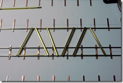
After this centre road was down, I made some jigs to set the distance of the next road from this centre road. These were made from some square brass channel that was a neat fit over the head of the code 70 rail and some larger C channel as the spacers.
Once the first rail of the next road is down, the second rail can be gauged from it using the normal gauges. I can lay rail this way reasonably quickly.
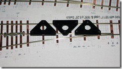
The black triangular gauges you can see were obtained from DD Wheelwrights in the Netherlands. The orange roller gauges are from Railway Engineering in the US.
I hope this has been of some assistance to those who wish to handlay their track. The principles are the same whether you are modelling P87 or other standards.
Cheers for now.

